Sunday, April 13, 2008
Difference between Architecture student and other fields student??
Seating infront of my drafting table i was just thinking of my past architecure studies and life...submissions,those late night studies , elevanth our model making , runnig for plotting , xeroxing the jurnals , computer failure befor the day of submissions....that is amazing..but whats the different between us and the other students like medical or enggi students? what do u think?? is there any diference?
Friday, April 11, 2008
THERMAL INSULATION USING FIBRE BOARDS
Introduction
The primary purpose of building’s thermal insulation is to control heat transfer and thereby protect a building from excessive heat loss during cold seasons and heat gain during hot seasons. This comfort effectively reduce the amount of energy required by a building’s heating and cooling equipment to maintain condition for human comfort.
Requirements for insulation
Insulations main function is to keep the heat in. To be effective, insulation must be the following:
resistant to heat flow
able to feel the space evenly and completely
Durable, and
For some location able withstand exposure to heat for moistures
Several different insulation materials may be used at different locations in the house envelope, depending on the space available for the insulation, ease of access and other installation requirements.
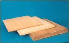
One of the type of these materials is fibre board, which often used for thermal insulation.

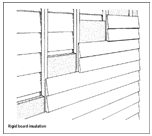
Section of the basement wall, with vertical metal supports for fibre board and soil sloped away from the wall .
Fibre boards are often used for the basement insulation treatment.Exterior basement insulation can play a number of roles within the basement envelope system.
Since heat-loss control and ground-water management are the critical roles that any exterior insulation must play.

Properties:
High heat resistance
Low density
Low thermal conductivity
Low heat storage
Structural strength
Excellent electrical insulation
Excellent sound absorption
Fast and simple installation
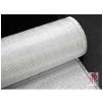
Glass Fibre Board
Glass fibre board is also a semi-rigid draining fibrous insulation, but it is less dense than the mineral fibre product, and shows more compression under the same load. The manufacturer compensated for this by providing additional R-value in the uncompressed state, to achieve a claimed R-value for in-ground placement where it would be compressed.
The in-situ thermal performance of this product was similar to that of adjacent products that experienced less compression. Substantial water movement at the outer face of the insulation was documented, confirming that drainage was taking place.
Types of glass fibre board:


Mineral Fibre Boards
Mineral fibre board is a dense, semi-rigid material that provides a drainage function because of the stratification of fibres and the voids between these fibres. The research showed substantial water movement at the board's outer face, which was in contact with the ground during periods of heavy rain and thaw.
The steady thermal performance of the board throughout these periods of water movement suggests that only the outer fibres of the insulation are involved in managing the water.
Advantages of fibre board :
Non-combustible.
Good insulation properties
High temperature resistance
Thermal stability and high mechanical strength.
Easily fabricated.
Cost effective
Non-corroding
Electrical resistance at high temperature.
Uses of fibre board

1 Fill air spaces particular in frame walls, floor and roofs
2 Wall sheathing or cavity fill, to increase strength as well as reduce heat loss:rigid roof insulation, perimeter slab insulation
3 Fill wall cavities and flat areas above ceilings.
Insulation boards reduce overheating

Mineral fibre or plastic board and glass fibre insulation boards add considerable thermal mass to a lightweight construction, preventing or reducing overheating in summer.
Insulation is designed to prevent heat loss from a building, but it can do more than this. They do this by acting as a thermal sink that absorbs heat and and prevents overheating on warm days.
The primary purpose of building’s thermal insulation is to control heat transfer and thereby protect a building from excessive heat loss during cold seasons and heat gain during hot seasons. This comfort effectively reduce the amount of energy required by a building’s heating and cooling equipment to maintain condition for human comfort.
Requirements for insulation
Insulations main function is to keep the heat in. To be effective, insulation must be the following:
resistant to heat flow
able to feel the space evenly and completely
Durable, and
For some location able withstand exposure to heat for moistures
Several different insulation materials may be used at different locations in the house envelope, depending on the space available for the insulation, ease of access and other installation requirements.
One of the type of these materials is fibre board, which often used for thermal insulation.

Section of the basement wall, with vertical metal supports for fibre board and soil sloped away from the wall .
Fibre boards are often used for the basement insulation treatment.Exterior basement insulation can play a number of roles within the basement envelope system.
Since heat-loss control and ground-water management are the critical roles that any exterior insulation must play.

Properties:
High heat resistance
Low density
Low thermal conductivity
Low heat storage
Structural strength
Excellent electrical insulation
Excellent sound absorption
Fast and simple installation
Glass Fibre Board
Glass fibre board is also a semi-rigid draining fibrous insulation, but it is less dense than the mineral fibre product, and shows more compression under the same load. The manufacturer compensated for this by providing additional R-value in the uncompressed state, to achieve a claimed R-value for in-ground placement where it would be compressed.
The in-situ thermal performance of this product was similar to that of adjacent products that experienced less compression. Substantial water movement at the outer face of the insulation was documented, confirming that drainage was taking place.
Types of glass fibre board:


Mineral Fibre Boards
Mineral fibre board is a dense, semi-rigid material that provides a drainage function because of the stratification of fibres and the voids between these fibres. The research showed substantial water movement at the board's outer face, which was in contact with the ground during periods of heavy rain and thaw.
The steady thermal performance of the board throughout these periods of water movement suggests that only the outer fibres of the insulation are involved in managing the water.
Advantages of fibre board :
Non-combustible.
Good insulation properties
High temperature resistance
Thermal stability and high mechanical strength.
Easily fabricated.
Cost effective
Non-corroding
Electrical resistance at high temperature.
Uses of fibre board


1 Fill air spaces particular in frame walls, floor and roofs
2 Wall sheathing or cavity fill, to increase strength as well as reduce heat loss:rigid roof insulation, perimeter slab insulation
3 Fill wall cavities and flat areas above ceilings.
Insulation boards reduce overheating


Mineral fibre or plastic board and glass fibre insulation boards add considerable thermal mass to a lightweight construction, preventing or reducing overheating in summer.
Insulation is designed to prevent heat loss from a building, but it can do more than this. They do this by acting as a thermal sink that absorbs heat and and prevents overheating on warm days.
Material Presentation- QUIET BOARD FOR SOUND INSULATION

DESCRIPTION:
IT is comprised of porous expanded polypropylene beads, which are formed into a semi rigid,water resistant panel.
The cylinder shaped beads are nonporous,but the hollow cores and cracks between adjacent beads allow sound to travel into the panel where it is absorbed.
APPLICATIONS:
IT can be installed as a wall panel, ceiling tile and hanging baffle.
Due to its water resistant properties, it may be used in marine applications.
Practical applications are:
indoor swimming pools, locker rooms, auditoriums, gymnasiums, classrooms,
arenas/stadiums, laboratories, computer rooms, clean rooms, food preparation areas, manufacturing facilities, machine shops, gun ranges and machine enclosures (i.e. compressors, pumps and air conditioner units).


PRODUCT AVAILABILITY:
1 x 24 x 48 inch white panels
2 x 24 x 48 inch white Panels
1 x 24 x 48 inch charcoal panels
2 x 24 x 48 inch charcoal panels
•Custom sizes available
SOUND TRANSMISSION LOSS
Freq. Hz 125 250 500 1000 2000 5000 STC
1“ (dB) 6 5 7 8 10 15 9
2“ (dB) 9 8 10 10 17 22 13
INSTALLATION:
Panels are placed directly on walls for sound insulation.
The surface on which the panels are placed is made rough for the panel to get stuck to the surface.
Placing of the panel starts from the bottom of the wall.
The panels are stuck to the wall with the help of adhesives.
The top panel sizes are cut according to the required dimension with the help of knife.
CUTTING METHOD:
Mark the QUIET BOARD panel at the desired dimensions.
Place the panel on the edge of a table or work bench. Doing this provides adequate space for the serrated knife to travel totally through thickness of the panel.
Using a straight edge as a guide, cut the panel with the serrated knife using a sawing motion.
Firmly hold the serrated knife at a 30 – 45 degree angle as you cut.
ADHESIVE

Loctite Power Grab:
IT is an advanced construction adhesive technology for multi-surface usage. It eliminates the need for nails and screws.
IT dries in approximately 24 hours.
Use 1 Tube per three 4 ft. x 8 ft. sheets (MEANS 2 PANELS IN 1 TUBE).
affiliate program
Architectural Presentation - ASBESTOS CEMENT SHEETS FOR HEAT INSULATION
Heat Insulation:
Heat insulation of any material is the resistance provided to the transfer of heat from the higher temp. to the lower temp.
Heat Resistance (R) is defined as: Number of hrs for 1 watt of energy to transfer heat from 1sqm of area with a temp difference of 1*C.
The heat resistance of any material is denoted by R. But for combination of materials it is U-value, which is the reciprocal of the R value.
Need of Heat insulation
The excessive use of artificial mechanisms for achieving the comfort level, has led to high emissions of chlorofluorocarbons & other poisonous gases.
Government of India has passed an Environment act, which will be applied in 2007.
According to this act the external envelop of any structure must have a U-value of min 0.5 W/m2K.

What is Asbestos cement?


Asbestos is a naturally occurring mineral found in underground rock formations.
Asbestos is also called as a magic mineral because no other substitute can match its properties.
Asbestos fiber is a major reinforcing component of Asbestos cement.
AC products consist of a mix of chrysotile fibers, cement & silicates of calcium & magnesium.
Heat Insulating properties of AC sheets


In general any material having open or closed pores is a good insulating material.
Asbestos cement has more of open pores therefore it is not as good as hair felt or straw boards.
If the AC sheets are waxed or coated with waterproofing material, it will seal the open pores & therefore the resistance to heat may increase.

The Thermal resistivity of AC sheets is 0.95 which is more compared to plastering, therefore they can be used as cladding on walls.
-The AC sheets also can be used for roofing, since rest of the materials do not meet the demand of U value=0.5
-Asbestos cement is also used for drainage pipes.
Advantages:

Longer life if properly fitted
Less noise from heavy rain and thermal movements
More attractive
Better thermal insulating properties
Rigid & Durable
Non corrosive, fire proof
Leak proof.
Acoustic insulation
Disadvantages:

They are heavier ,thus it is more expensive to transport and requires a stronger roof structure.
Brittleness causes a high rate of waste due to breakage during transport and installation..
Labour intensive due to weight and brittleness.
The corners of the sheets must be mitred prior to fitting and holes for the fixing screws must be drilled.
Easily discolors with dust and algae.
The manufacture, processing & discarding of asbestos products presents hazards to health.
Sizes:

Standard lengths-3, 2.75, 2.5, 2.25, 2, 1.75, 1.5 m
Thickness-6mm
Depth-48mm
Overall width-1050 mm
Effective depth-1010 mm
Architectural Presentation-RAFT FOUNDATION
FOUNDATION
MAIN FUNCTION IS TO CARRY THE LOAD OF THE SUPERSTRUCRURE TO THE SUBSOIL .
SELECTION OF FOUNDATION
THE TYPE OF THE FOUNDATION IS MAINLY DEPEND UPON THE FOLLOWING THINGS :-
TYPE OF CONSTRUCTION.
LOAD BEARING CAPACITY OF OF SOIL.
WHEN STRUCTURE HAS ONLY LIGHT LOADING SUCH AS DOMESTIC DWELLING HOUSE,THE RAFT OR MASS CONCRETE STRIP FOUNDATION IS SUFFICIENT.
THE PLAN SIZE OF A FOUNDATION IS DERIVED FROM
LOAD/
BEARING CAPACITY OF SOIL
TYPES OF THE FOUNDATIONS
STRIP FOUNDATIONS.
ISOLATED OR PAD FOUNDATIONS.
RAFT FOUNDATIONS.
COMBINATION OF ABOVE FOUNDATIONS.
PILED FOUNDATION.
STRIP FOUNDATIONS
REINFORCED CONCRETE STRIP FOUNDATIONS ARE USED TO SUPPORT AND TRANSMIT THE LOADS OF HEAVY WALLS.

ISOLATED OR PAD FOUNDATIONS
THIS TYPE OF FOUNDATION IS USED TO SUPPORT AND TRANSMIT THE LOADS FROM PIERS AND COLUMN.

RAFT FOUNDATION
THE PRINCIPAL OF ANY RAFT FOUNDATION IS
TO SPREAD THE LOAD OF THE ENTIRE AREA OF THE SITE.
A RAFT FOUNDATION NORMALLY CONSISTS OF A
CONCRETE SLAB WHICH EXTENDS OVER THE
ENTIRE AREA. IT MAY BE STIFFENED BY RIBS OR
BEAMS INCORPORATED INTO THE FOUNDATION.
THEY ARE MADE UP OF CONCRETE AND HEAVILY REINFORCED WITH STEEL,SO ENTIRE FOUNDATION WILL ACT AS A UNIT
THE RAFT FOUNDATIONS HAVE THE ADVANTAGE OF REDUCING DIFFERENTIAL SETTLEMENTS AS THE CONCRETE SLAB RESISTS DIFFERENTIAL MOVEMENTS BETWEEN LOADING POSITIONS.

WHERE RAFT FOUNDATIONS ARE USE ?
THE RAFT FOUNDATIONAS ARE USED WHERE THE COLUMN LOAD ARE HEAVY AND THUS REQUIRING LARGE BASES.
WHERE THE BEARING CAPACITY OF SOIL IS LOW, RESULTING IN THE NEED OF LARGE BASE.
THEY ARE USED ON SOFT COMPRESSIBLE SUBSOIL SUCH AS SOFT CLAY OR PIT.
TYPES OF RAFT FOUNDATION
RAFT FOUNDATIONS CAN BE CONSIDER IN THREE TYPES
SOLID SLAB RAFTS.
BEAM AND SLAB RAFTS.
CELLULAR RAFTS.
SOLID SLAB RAFT FOUNDATION
THESE ARE CONSTRUCTED OF UNIFORM THICKNESS OVER THE WHOLE RAFT AREA.
THE EFFECT OF THE LOAD FROM COLUMN AND THE GROUND PRESSURE IS TO CREATE AREAS OF TENTION UNDER THE COLUMN AND THE AREAS OF TENTION IN THE UPPER PART OF THE RAFT BETWEEN THE COLUMN.
OFTEN THE NOMINAL MESH OF REINFORCEMENT IS PROVIDED IN THE FACES WHERE TENTION DOES NOT OCCUR TO CONTROL SHRINKAGE CRACKING OF THE CONCRETE.

BEAM AND SLAB RAFT FOUNDATION
BEAM AND SLAB RAFTS ARE ALTERNATIVES TO THE SOLID SLAB RAFT AND ARE USED WHERE POOR SOILS ARE UNCOUNTERED.
THE BEAMS ARE USED TO DISTRIBUTE THE COLUMN LOAD OVER THE AREA OF THE RAFT, THAT RESULTS IN THE REDUCTION OF THE SLAB THICKNESS.
THE BEAMS CAN BE UPSTAND OR DOWNSTAND DEPENDING UPON THE BEARING CAPACITY OF SOIL NEAR THE SURFACE.
DOWNSTAND BEAMS WILL GIVE A SAVING ON EXCAVATION COSTS WHEREAS UPSTAND BEAMS CREATE A USABLE VOID BELOW THE GROUNG FLOOR IF A SUSPENDED SLAB IS USED.

CELLULAR RAFT FOUNDATION
THESE TYPE OF FOUNDATIONS ARE USED ON SOFT COMPRESSIBLE SUBSOIL SUCH AS SOFT CLAY OR PIT.
SO DURING CURING PROCESS THE REINFORCEMENT AT THE BOTTOM SHOULD BE PROVIDED TRUE LEVEL SURFACE FROM WHICH THE REINFORCEMENT CAN BE POSITIONED.
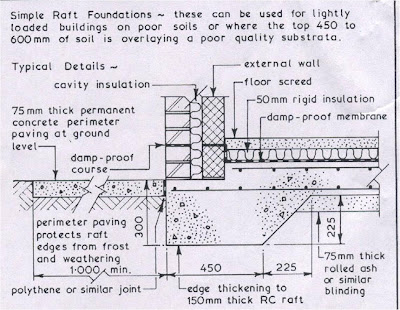
A BLINDING LAYER OF 50 TO 75mm THICK OF WEAK CONCRETE OR COURSE SAND SHOULD BE PLACED UNDER REINFORSED CONCRETE (RAFT) FOUNDATION.
THE FUNCTION OF THIS LAYER IS TO FILL IN ANY WEAK POCKETS ENCOUNTERED DURING EXCAVATION.
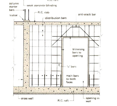
REINFORCEMENT DETAIL OF RAFT FOUNDATION

MAIN FUNCTION IS TO CARRY THE LOAD OF THE SUPERSTRUCRURE TO THE SUBSOIL .
SELECTION OF FOUNDATION
THE TYPE OF THE FOUNDATION IS MAINLY DEPEND UPON THE FOLLOWING THINGS :-
TYPE OF CONSTRUCTION.
LOAD BEARING CAPACITY OF OF SOIL.
WHEN STRUCTURE HAS ONLY LIGHT LOADING SUCH AS DOMESTIC DWELLING HOUSE,THE RAFT OR MASS CONCRETE STRIP FOUNDATION IS SUFFICIENT.
THE PLAN SIZE OF A FOUNDATION IS DERIVED FROM
LOAD/
BEARING CAPACITY OF SOIL
TYPES OF THE FOUNDATIONS
STRIP FOUNDATIONS.
ISOLATED OR PAD FOUNDATIONS.
RAFT FOUNDATIONS.
COMBINATION OF ABOVE FOUNDATIONS.
PILED FOUNDATION.
STRIP FOUNDATIONS
REINFORCED CONCRETE STRIP FOUNDATIONS ARE USED TO SUPPORT AND TRANSMIT THE LOADS OF HEAVY WALLS.

ISOLATED OR PAD FOUNDATIONS
THIS TYPE OF FOUNDATION IS USED TO SUPPORT AND TRANSMIT THE LOADS FROM PIERS AND COLUMN.

RAFT FOUNDATION
THE PRINCIPAL OF ANY RAFT FOUNDATION IS
TO SPREAD THE LOAD OF THE ENTIRE AREA OF THE SITE.
A RAFT FOUNDATION NORMALLY CONSISTS OF A
CONCRETE SLAB WHICH EXTENDS OVER THE
ENTIRE AREA. IT MAY BE STIFFENED BY RIBS OR
BEAMS INCORPORATED INTO THE FOUNDATION.
THEY ARE MADE UP OF CONCRETE AND HEAVILY REINFORCED WITH STEEL,SO ENTIRE FOUNDATION WILL ACT AS A UNIT
THE RAFT FOUNDATIONS HAVE THE ADVANTAGE OF REDUCING DIFFERENTIAL SETTLEMENTS AS THE CONCRETE SLAB RESISTS DIFFERENTIAL MOVEMENTS BETWEEN LOADING POSITIONS.

WHERE RAFT FOUNDATIONS ARE USE ?
THE RAFT FOUNDATIONAS ARE USED WHERE THE COLUMN LOAD ARE HEAVY AND THUS REQUIRING LARGE BASES.
WHERE THE BEARING CAPACITY OF SOIL IS LOW, RESULTING IN THE NEED OF LARGE BASE.
THEY ARE USED ON SOFT COMPRESSIBLE SUBSOIL SUCH AS SOFT CLAY OR PIT.
TYPES OF RAFT FOUNDATION
RAFT FOUNDATIONS CAN BE CONSIDER IN THREE TYPES
SOLID SLAB RAFTS.
BEAM AND SLAB RAFTS.
CELLULAR RAFTS.
SOLID SLAB RAFT FOUNDATION
THESE ARE CONSTRUCTED OF UNIFORM THICKNESS OVER THE WHOLE RAFT AREA.
THE EFFECT OF THE LOAD FROM COLUMN AND THE GROUND PRESSURE IS TO CREATE AREAS OF TENTION UNDER THE COLUMN AND THE AREAS OF TENTION IN THE UPPER PART OF THE RAFT BETWEEN THE COLUMN.
OFTEN THE NOMINAL MESH OF REINFORCEMENT IS PROVIDED IN THE FACES WHERE TENTION DOES NOT OCCUR TO CONTROL SHRINKAGE CRACKING OF THE CONCRETE.

BEAM AND SLAB RAFT FOUNDATION
BEAM AND SLAB RAFTS ARE ALTERNATIVES TO THE SOLID SLAB RAFT AND ARE USED WHERE POOR SOILS ARE UNCOUNTERED.
THE BEAMS ARE USED TO DISTRIBUTE THE COLUMN LOAD OVER THE AREA OF THE RAFT, THAT RESULTS IN THE REDUCTION OF THE SLAB THICKNESS.
THE BEAMS CAN BE UPSTAND OR DOWNSTAND DEPENDING UPON THE BEARING CAPACITY OF SOIL NEAR THE SURFACE.
DOWNSTAND BEAMS WILL GIVE A SAVING ON EXCAVATION COSTS WHEREAS UPSTAND BEAMS CREATE A USABLE VOID BELOW THE GROUNG FLOOR IF A SUSPENDED SLAB IS USED.

CELLULAR RAFT FOUNDATION

THESE TYPE OF FOUNDATIONS ARE USED ON SOFT COMPRESSIBLE SUBSOIL SUCH AS SOFT CLAY OR PIT.
SO DURING CURING PROCESS THE REINFORCEMENT AT THE BOTTOM SHOULD BE PROVIDED TRUE LEVEL SURFACE FROM WHICH THE REINFORCEMENT CAN BE POSITIONED.
A BLINDING LAYER OF 50 TO 75mm THICK OF WEAK CONCRETE OR COURSE SAND SHOULD BE PLACED UNDER REINFORSED CONCRETE (RAFT) FOUNDATION.
THE FUNCTION OF THIS LAYER IS TO FILL IN ANY WEAK POCKETS ENCOUNTERED DURING EXCAVATION.
REINFORCEMENT DETAIL OF RAFT FOUNDATION


CIRCULATION PATTERN OF CHANDIGARH,Inida.

Formation of the city
Post partition in 1947, the Indian state of Punjab needed a new capital to replace Lahore.
The new capital of India was envisioned as the modern capital of India by Jawaharlal Nehru.
The site chosen was a farmland of 24 villages.
Criteria for selection of site
Location, central
Water supply available in the form of seasonal rivers.
Comfortable climate, i.e. a subtropical monsoon.
Proximity to building materials, required for large scale construction.
HISTORY
Mayer Nowiki prepared a Master Plan for a population of 500 thousand based on a system of a low density neighborhood and defined by a grid of roads.Roads were slightly curved to follow the contours of the site.
Le Corbusier simplified Mayer’s Curvilinear system by adopting the grid iron pattern of straight roads.
Professional approach linking the body of the city with its symbolic head was bounded by Multi-Storied buildings on one side and Parallel land on the other side.
Other main artery leads from the railway station and terminates at university.
CONCEPT
In the revised master plan Le Corbusier developed a checkerboard of rectangles called “Sectors” each measuring 800m x 1200m enclosed by roads for fast moving traffic.
Purpose: to fulfill 4 basic functions.
a)Living.
b)Circulation.
c)Working.
d)Care of body and spirit.
Biological Entity
Head – The Capitol area.
Heart – The City Centre.
Limbs – Work areas.
Care of body – Linear continuous parks,
and Spirit Leisure area systems,
Sukhana Lake.

HIERARCHY OF TRAFFIC CIRCULATION

V1: Arterial inter-state roads,
V2: Major boulevards,
V3: Sector-definers,
V4: Shopping streets, usually
linking with those in
adjoining sectors,
V5: Neighborhood streets,
typically a loop road going
round the interior of the
sector,
V6: Access lanes to houses,
V7: Pedestrian paths and cycles
tracks; to be planned
throughout the city,
meandering through its
green spaces.


PLANNING
The typical sector is a self sufficient neighborhood, with its own shopping centre, schools and other community facilities.
For outdoor recreation, the sector greens cut through the heart of each neighborhoods enabling the residents to view without obstruction the changing panorama of the Shivalik range.
A sector is traversed only by slow traffic streets, the fast traffic roads are being restricted to its periphery.
This ensures tranquility and safety within the living spaces. A novel feature of Chandigarh’s master plan is the scheme of segregation, called the 7Vs (les Sept Voiles) developed by Le Courbusier.
The system of roads symbolizes the structure of a tree, hierarchy and progressively branching out from the stem to leaf and proportionately reduce in size in accordance with the quantum of life to be carried.

STRUCTURAL ELEMENTS AND THEIR FIRE RESISTANCE
INTRODUCTION
The fire resistance of a structural member may be defined as its ability to withstand exposure to fire without loss of load bearing function or ability to act as a barrier to spread of fire. This provides time to permit people to evacuate a building before it collapses and is essential in confining fire to the compartment in which it starts.
Prediction of the fire behavior of structural members involves the calculation of fire temperatures and the temperature, deformation and strength of the members .
FIRE RESISTANT CONSTRUCTION.
In a fire resistant construction, the maximum use of non-combustible material should be encouraged.the structural members like beams ,columns,floors,roofs etc. should be constructed in such a way that they should continue to function as structural members at least for the period which may be sufficient for the occupants to escape.
STRENGTH OF MEMBERS
When temperature rises in fire-exposed members, their strength is reduced. If the fire load is sufficient and the duration of the fire long enough, a stage will be reached at which the strength of the member will no longer be adequate to support the structural load. The fire load that is just sufficient to reduce strength to this critical point is defined as the critical fire load.
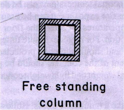
COLUMNS AND BEAMS
Reinforced concrete structures should be preferred to steel structures as it is liable to twist ,sag under heavy fire.
If steel is used it should be protected by using concrete,hollow clay tiles, bricks ,and plaster .the treatment given to the columns is given below.
The cover of the protective material like tiles or bricks etc. should be all around the members at least 10 cm. Thick.
The cover of concrete for reinforced concrete members should be sufficient to enable the members function under fire for max. time.
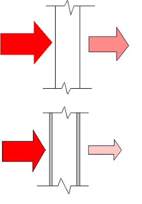
For beams and columns the higher ratio of the surface exposed to fire greater is the fire resistance.
Beams and columns with membrane enclosure protection will have less surface area exposed to fire.
FIRE RESISTANCE OF STRUCTURAL STEELWORK
Although steel is non combustible material it does not behave very well under fire conditions.
Achieved fire resistance for steel members encased in concrete depends upon the thickness of the protective concrete cover,concrete mixture and structural restraint .
For protection of structural elements following methods are adopted :
1)cladding
2)Cooling the element with water
3)Intumescent coatings
4)design of a composite section


LOAD BEARING CONSTRUCTION
In case wooden partition has to be made fire resistant it should be covered with metal lath and plaster.
The load bearing walls should be plastered with fire resistive mortar.
Cavity wall provides a good option for fire resistant construction.
The fire resistance of load bearing walls should not be less than two hours
The partition walls should be of fire resistant material;in general R.C.C., bricks, hollow concrete blocks, tiles or timber.the material should be treated in such a way that they should have fire resistance of not less than one hour.
The load bearing walls should be thicker in section so that they may successfully act as fire barrier for a considerable time.
There are also special fire-retardant paints and coatings that can substantially reduce the flame-spread rating of an interior surface.
Fire resistance of construction with cavity air space will be greater than identical weight construction without airspace
STAIRCASE
For stairs a higher standard of fire resistance is required.
R.C.C. stairs are considered best .
The enclosing walls of the main staircase should have a fire resistance of at least 1 hour.
Access to the staircase should be through doors having fire resistance of at least ½ hour.
All the fire escape stairs should be directly connected to ground floor and their entrance should be away from the internal staircase of a building.
ROOFS
Flat roof should be encouraged as far as possible.
Where sloping roof is necessary either due to site conditions or architectural reasons the ceilings of the sloped roof should be made up of fire resistant material by fixing asbestos cement boards , fiberboard to its framework.
In the installation of roofing, wood cant strips, roof curbs, nailing strips are permitted in noncombustible construction. Roof sheathing and sheathing supports of wood are also permitted provided:
They are installed above a concrete deck
The concealed space does not extend more than 1m above the deck
Openings through the concrete deck are located in noncombustible shafts
Parapets are provided at the deck perimeter extending at least 150mm above the sheathing.
The noncombustible parapets and shafts are required to prevent roof materials igniting from flames projecting from openings in the building face or roof deck.
In buildings that must be of noncombustible construction the roof coverings must have a fire classification of Class A, B or C. In such cases the use of fire-retardant treated wood shakes and shingles on sloped roofs is allowed.
FLOORING
Fire resisting material should be used in construction of flooring
In case of wooden floors thicker joists spaced at greater distance apart should be used.
Fire stops should be provided in wooden floors at suitable intervals
Flooring made from materials like concrete, brick, ceramic tile etc. is considered to be most suitable for fire resistant construction.
The fire resistance of a structural member may be defined as its ability to withstand exposure to fire without loss of load bearing function or ability to act as a barrier to spread of fire. This provides time to permit people to evacuate a building before it collapses and is essential in confining fire to the compartment in which it starts.
Prediction of the fire behavior of structural members involves the calculation of fire temperatures and the temperature, deformation and strength of the members .
FIRE RESISTANT CONSTRUCTION.
In a fire resistant construction, the maximum use of non-combustible material should be encouraged.the structural members like beams ,columns,floors,roofs etc. should be constructed in such a way that they should continue to function as structural members at least for the period which may be sufficient for the occupants to escape.
STRENGTH OF MEMBERS
When temperature rises in fire-exposed members, their strength is reduced. If the fire load is sufficient and the duration of the fire long enough, a stage will be reached at which the strength of the member will no longer be adequate to support the structural load. The fire load that is just sufficient to reduce strength to this critical point is defined as the critical fire load.
COLUMNS AND BEAMS
Reinforced concrete structures should be preferred to steel structures as it is liable to twist ,sag under heavy fire.
If steel is used it should be protected by using concrete,hollow clay tiles, bricks ,and plaster .the treatment given to the columns is given below.
The cover of the protective material like tiles or bricks etc. should be all around the members at least 10 cm. Thick.
The cover of concrete for reinforced concrete members should be sufficient to enable the members function under fire for max. time.
For beams and columns the higher ratio of the surface exposed to fire greater is the fire resistance.
Beams and columns with membrane enclosure protection will have less surface area exposed to fire.
FIRE RESISTANCE OF STRUCTURAL STEELWORK
Although steel is non combustible material it does not behave very well under fire conditions.
Achieved fire resistance for steel members encased in concrete depends upon the thickness of the protective concrete cover,concrete mixture and structural restraint .
For protection of structural elements following methods are adopted :
1)cladding
2)Cooling the element with water
3)Intumescent coatings
4)design of a composite section


LOAD BEARING CONSTRUCTION
In case wooden partition has to be made fire resistant it should be covered with metal lath and plaster.
The load bearing walls should be plastered with fire resistive mortar.
Cavity wall provides a good option for fire resistant construction.
The fire resistance of load bearing walls should not be less than two hours
The partition walls should be of fire resistant material;in general R.C.C., bricks, hollow concrete blocks, tiles or timber.the material should be treated in such a way that they should have fire resistance of not less than one hour.
The load bearing walls should be plastered with fire resistive mortar.
Cavity wall provides a good option for fire resistant construction.
The fire resistance of load bearing walls should not be less than two hours
The partition walls should be of fire resistant material;in general R.C.C., bricks, hollow concrete blocks, tiles or timber.the material should be treated in such a way that they should have fire resistance of not less than one hour.
The load bearing walls should be thicker in section so that they may successfully act as fire barrier for a considerable time.
There are also special fire-retardant paints and coatings that can substantially reduce the flame-spread rating of an interior surface.
Fire resistance of construction with cavity air space will be greater than identical weight construction without airspace
STAIRCASE
For stairs a higher standard of fire resistance is required.
R.C.C. stairs are considered best .
The enclosing walls of the main staircase should have a fire resistance of at least 1 hour.
Access to the staircase should be through doors having fire resistance of at least ½ hour.
All the fire escape stairs should be directly connected to ground floor and their entrance should be away from the internal staircase of a building.
ROOFS
Flat roof should be encouraged as far as possible.
Where sloping roof is necessary either due to site conditions or architectural reasons the ceilings of the sloped roof should be made up of fire resistant material by fixing asbestos cement boards , fiberboard to its framework.
In the installation of roofing, wood cant strips, roof curbs, nailing strips are permitted in noncombustible construction. Roof sheathing and sheathing supports of wood are also permitted provided:
They are installed above a concrete deck
The concealed space does not extend more than 1m above the deck
Openings through the concrete deck are located in noncombustible shafts
Parapets are provided at the deck perimeter extending at least 150mm above the sheathing.
The noncombustible parapets and shafts are required to prevent roof materials igniting from flames projecting from openings in the building face or roof deck.
In buildings that must be of noncombustible construction the roof coverings must have a fire classification of Class A, B or C. In such cases the use of fire-retardant treated wood shakes and shingles on sloped roofs is allowed.
FLOORING
Fire resisting material should be used in construction of flooring
In case of wooden floors thicker joists spaced at greater distance apart should be used.
Fire stops should be provided in wooden floors at suitable intervals
Flooring made from materials like concrete, brick, ceramic tile etc. is considered to be most suitable for fire resistant construction.
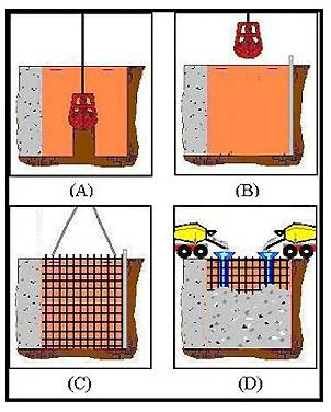
DIAPHRAGM WALLS
Diaphragm walls refers to the construction of in-situ retaining vertical walls by deep trench excavation method.
Stability of the sides of the excavation is ensured by bentonite slurry. Hence these types of walls are also termed at times as ‘slurry walls’
The wall is constructed in panels and the length of typical panel is between 2.5 to 7m.
Standard methods of constructing retaining walls require temporary form work and supports. These become uneconomical after a certain depth.
The construction of the work above ground cannot proceed till the basement work is complete. This involves more time for construction.
Use of diaphragm wall construction eliminates the need for formwork and temporary support and also allows above ground construction to proceed along with basement construction

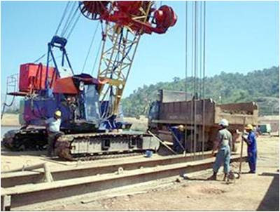
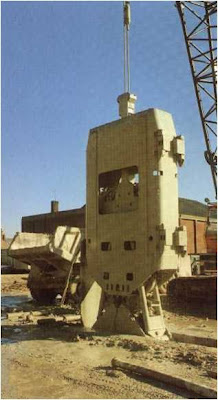
Purpose built grabs or milling machines called as hydromills are used to do the excavation.
Since the wall is cast in panels special care has to be taken to make the joints between the panels watertight.
Water bars are constructed within the construction joints to prevent water leakage through them.
Standard widths of the walls range from 600,800, 1000 and 1200mm.
BENTONITE SLURRY
Bentonite slurry is a clay mixed with water which possesses ‘Thicksotropic’ property. That means that when it is left undisturbed it acts as a ‘gel’ and when it is moved it acts like a liquid. The bentonite slurry is poured into the excavation and it seeps into the adjoining soil forming a cake which prevents the sides from caving in.The bentonite is removed while concreting by displacement.
The depth of diaphragm walls can reach 50 to 80m.
The tolerance for verticality is normally 1:200
This type of construction method is called ‘Top down basement construction’
This allows for above ground construction simultaneously with excavation of basement.
Typical Applications:
Deep basements
Underground tanks
Access shafts
Road and rail under passes
Tunnels
Multilevel under ground parking


Stability of the sides of the excavation is ensured by bentonite slurry. Hence these types of walls are also termed at times as ‘slurry walls’
The wall is constructed in panels and the length of typical panel is between 2.5 to 7m.
Standard methods of constructing retaining walls require temporary form work and supports. These become uneconomical after a certain depth.
The construction of the work above ground cannot proceed till the basement work is complete. This involves more time for construction.
Use of diaphragm wall construction eliminates the need for formwork and temporary support and also allows above ground construction to proceed along with basement construction

Purpose built grabs or milling machines called as hydromills are used to do the excavation.
Since the wall is cast in panels special care has to be taken to make the joints between the panels watertight.
Water bars are constructed within the construction joints to prevent water leakage through them.
Standard widths of the walls range from 600,800, 1000 and 1200mm.
BENTONITE SLURRY
Bentonite slurry is a clay mixed with water which possesses ‘Thicksotropic’ property. That means that when it is left undisturbed it acts as a ‘gel’ and when it is moved it acts like a liquid. The bentonite slurry is poured into the excavation and it seeps into the adjoining soil forming a cake which prevents the sides from caving in.The bentonite is removed while concreting by displacement.
The depth of diaphragm walls can reach 50 to 80m.
The tolerance for verticality is normally 1:200
This type of construction method is called ‘Top down basement construction’
This allows for above ground construction simultaneously with excavation of basement.
Typical Applications:
Deep basements
Underground tanks
Access shafts
Road and rail under passes
Tunnels
Multilevel under ground parking


Subscribe to:
Posts (Atom)
Other interesting posts
